
Here you can find two different implementations of a line follower robot (Acrobot). One using two sensors and another one using one more. The last one as you will see later will run smoothly than first one. Both programs were made in assembly language and the base robot was built enterily with standard RCX components and LEGO pieces. It includes just two/three light sensors, and two engines for each wheel.
Two sensors
The workflow of this implementation is quite simple as you can see in the picture:
- If both sensors are inside the line just go straight because we're on the line.
- If one sensor is outside and the other inside, turn in the direction of the one that is inside, because there's where the line is.
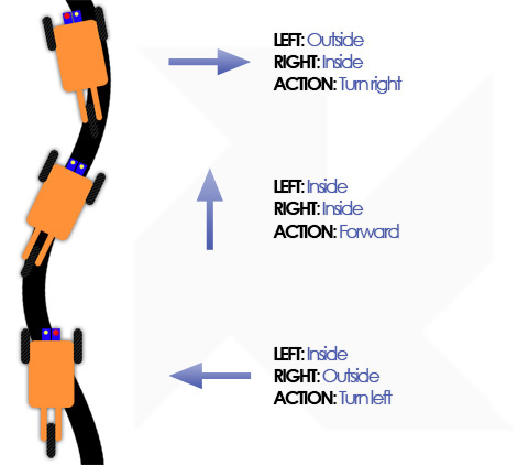
The problem come when we have both sensors outside of the line. This problem can achieve in several cases, depending of the architecture and logic of your robot.
But basically if you don't refresh quite often the sensors or if your speed is so high you can end up with your robot out from the line in every corner.
One first trick was just to put one fixed or random direction to go back to the line (As you can see also in the video some people used this way). The problem is that you should be very lucky to get the correct direction everytime :)
So the solution was to store the last sensor that leaves the line so I could know in which direction I leave the line and I'll turn accordingly. This was the best improvement of speed that I made in my robot as I didn't need to care about him going out from the path, he'll know how to come back.
Three sensors
In the previous implementation when the robot needed to turn it rotate one wheel in one direction and the other in the opposite getting a fast turn. The problem is that this turns are very aggressive even in small curves and it doesn't looks nice so I tried to make them smoother.
After adding a new sensor I got more states to control. The desired position of the sensors over the line would be two sensors out of the line (left and right) and one central sensor over the line. In this conditions the robot should go straight. The new states for turning can be visible in the picture below:
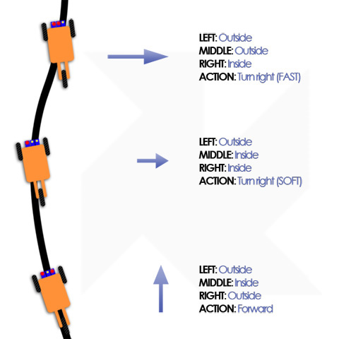
If the center and the right sensors are in the line it means the robot is moving to the left going away from the line, so It need to turn soft to the right. This soft movement is just moving wheel while leaving without poner the left one, so it turn smoothly.
If just the right sensor is in the line is because we're moving further from the path so we need to turn fast to the path direction. This fast turn is the same as in the previous implementation, each wheel in one direction.
In the other case is easy to understand how to get the robot into the path, as in the two sensors implementation.
Sensors reading
Apart from that I think the most interesting in the code is the implementation of the interruptions and the activSensor routines, that I've implemented allowing to pass one number in r0 to tell the routine which port do you want to read, so you can use like follow:
mov #0, r0 ; Get the light value from sensor 3
jsr @_activSensor ; write sensor value into r0 mov r0, r3 ; r3 value of light sensor (2) mov #2, r0 ; Get the light value from sensor 1
jsr @_activSensor ; write sensor value into r0 mov r0, r4 ; r4 value of light sensor (1) /////////////////
In action
Here you could see our winner on a LEGO Robots competition held in Vitus Bering University (Denmark):